Micro Combustor
Thermophotovoltaic Energy Conversion
This project - now Mesodyne - was based on a photonic material that when heated, only emitted blackbody radiation over a very narrow frequency band. This could be matched to a solar cell tuned to the same frequency to turn heat into electricity with a very high thermal efficiency. I worked on the design and fabrication of the combustors to heat this assembly in January of 2018, focusing on two major problems: optimal fin design to provide an evenly heated surface with no hot spots, and fuel and air mixing. The team had a previous smaller prototype and was trying to scale the system up by 400% to a 40mm x 40mm square burner
Combustion Chamber Design
With the help of some NASA papers on fuel combustion and some conversations with my mentor, we explored and experimented with traditional flame combustion, but quickly realized that we could not get stable, complete combustion in the small package we were working with. Rather than try to scavenge the unburned fuel with a catalyst, we opted to put the entire fuel and air mixture through a catalyst painted on heat conducting fins. We could used the fin placement and density to determine where and how much heat we applied to any one section of the plate. The problem then largely centered on how to optimize fin placement and deliver a homogenous air and fuel mixture to the assembly.
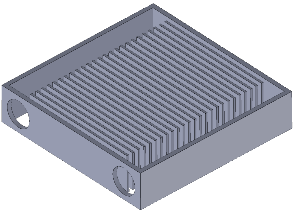
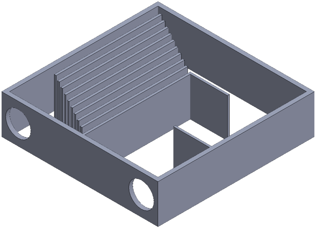
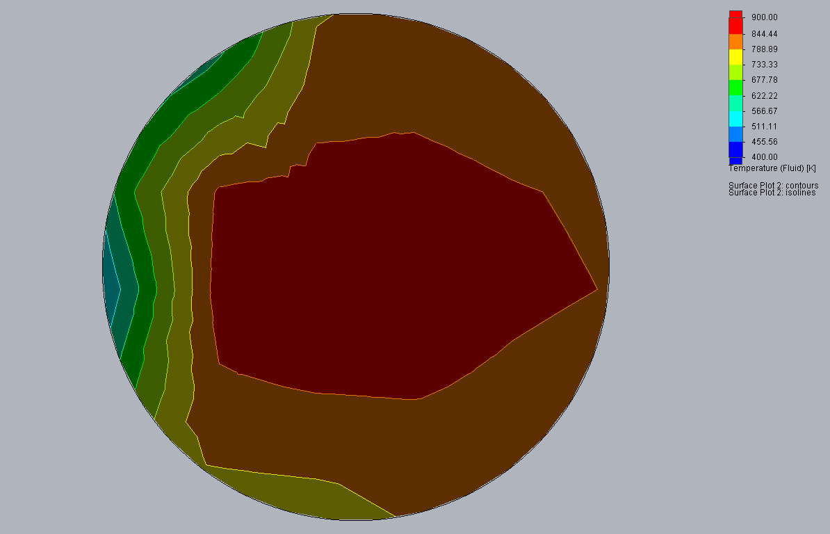
We created several CAD mockups, and used Solidworks CFD to model heat flow. I found that modeling the burner as introducing hot air at the flame temperature of propane matched our experimental results very well, and used this to model a number of burner configurations. Here’s a picture of the exit exhaust temperature profile:
Air-Fuel Mixing
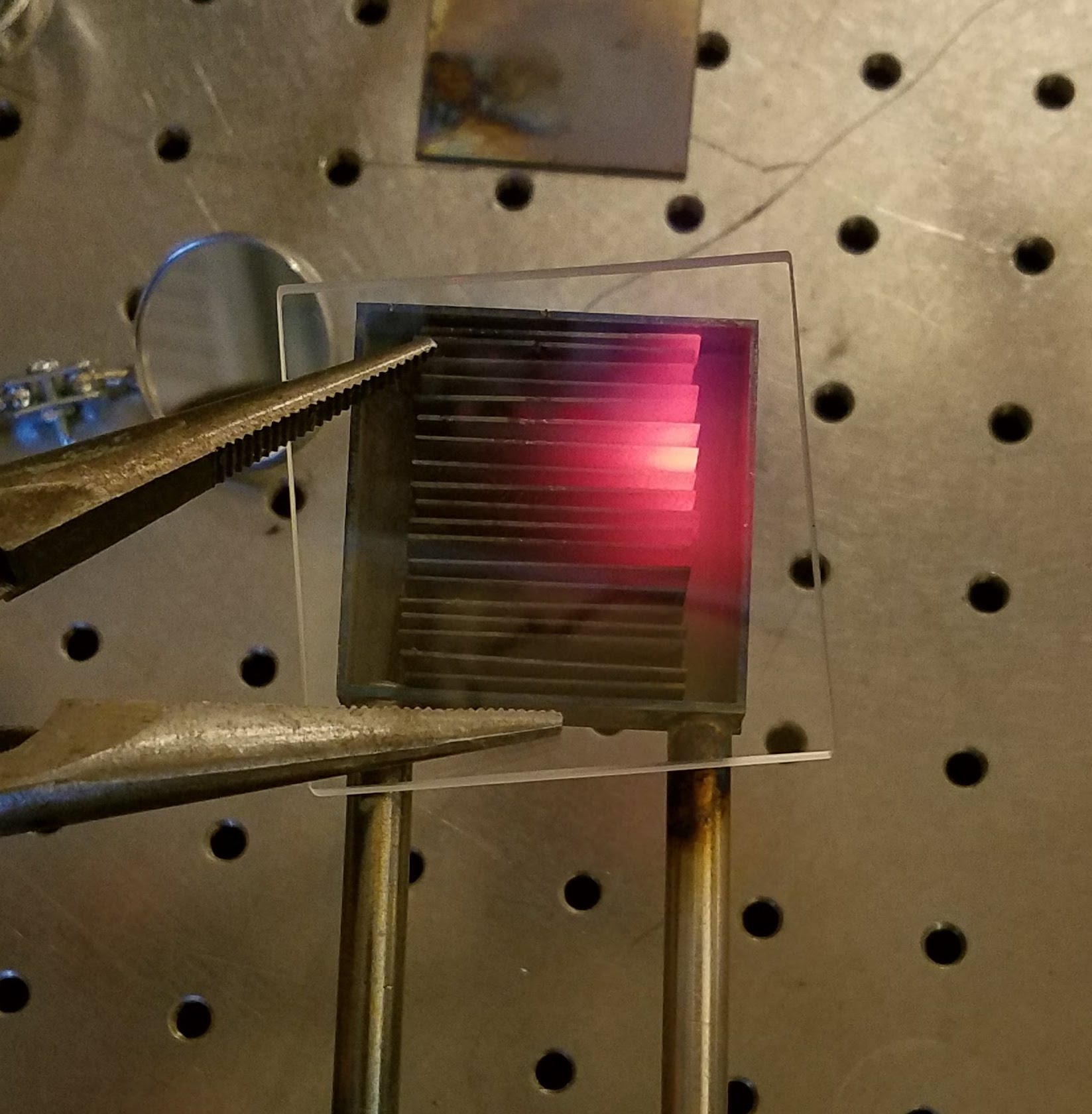
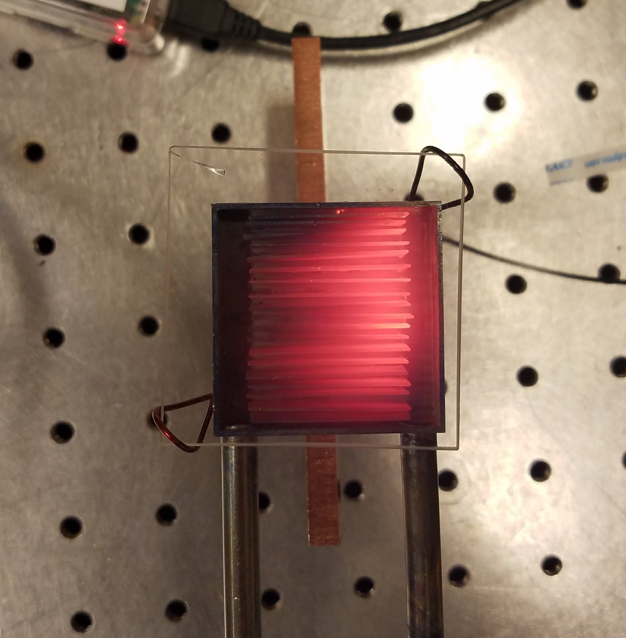
Due to the small size and laminar flow in this 4cm x 4cm device, our air and fuel would not naturally mix well before entering our burner, and would cause hot and cold spots from incomplete combustion as seen in the first image. The second image shows the result of very close to ideal mixing and even combustion. These images were taken with a quartz window installed for testing instead of the metal cap used in the final assembly.
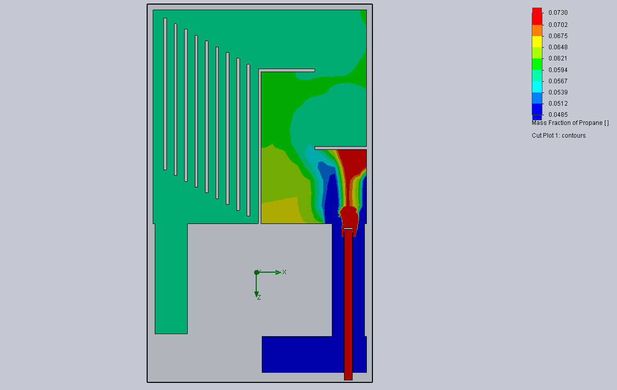
To resolve this problem, we set up our exhaust gas analyzer and found that we we had significant unburned air and fuel in our exhaust. By the time we reduced fuel flow to the point where we had no extra fuel in our exhaust, the exhaust oxygen levels were about 10% - clearly not a good use of air when we want efficient heat. I then turned to a number of mixing simulations, including this one, to determine the best approach to this problem:
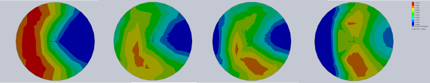
Our final design settled on closely spaced parallel fins and changing the injection system for the propane. We ended up injecting propane at right angles to our air stream in our intake manifold, with our propane injection point placed at just under halfway across the air stream to provide the best mixing scenario. Here’s the CFD results for the propane concentration at the burner entrance with various fuel injection locations upstream. These CFD results matched our experimental results very well - large color differences resulted in high concentrations of unburned fuel and excess oxygen, small color differences correlated with complete combustion and even heat.
Fabrication
Fabricating materials that can operate at 1200ºC is a challenge. However, we found that we could use a boron doped nickel braze, which locally lowered the melting point of our Inconel until the boron diffused through the material. So, we would spot weld our fins onto our flat plates, place the exterior box around the assembly, tack small pieces of brazing foil where we wanted joints, and then place the entire assembly in a vacuum oven for several hours to braze and seal the joints and diffuse the boron.
Testing Photos
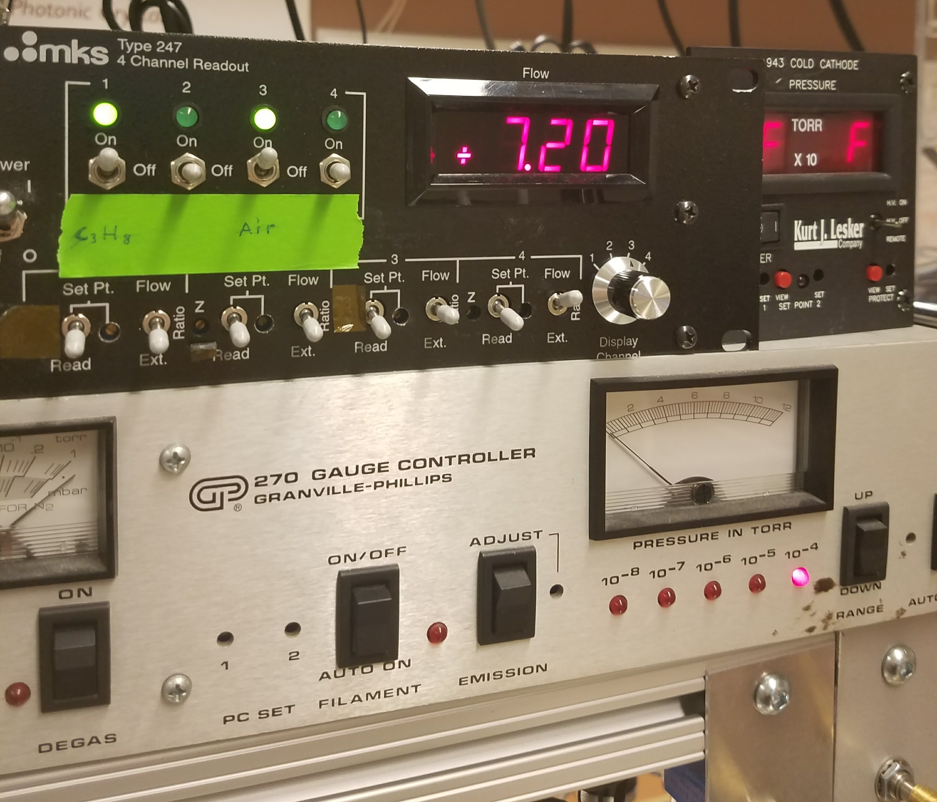
Flow Controller
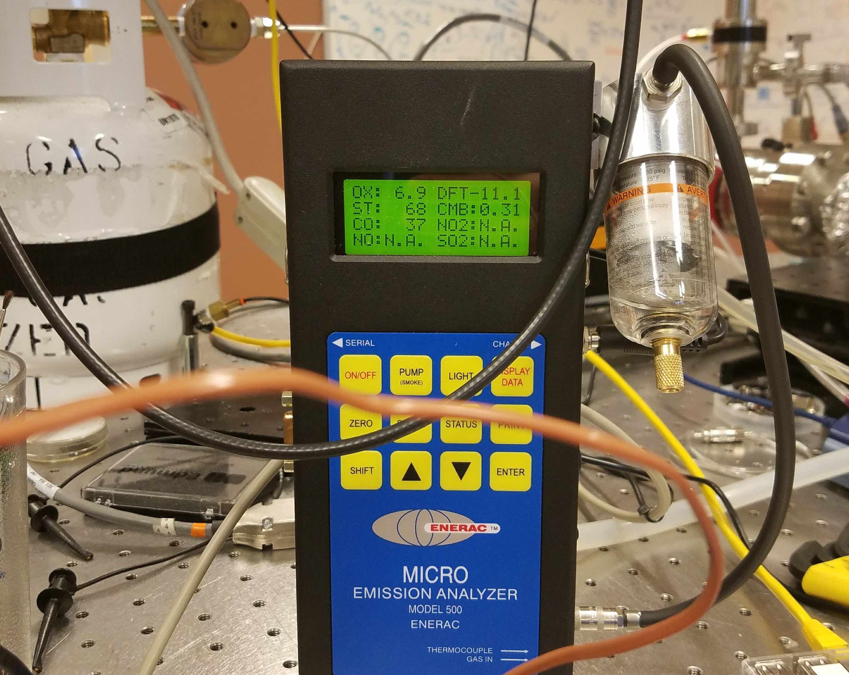
Exhaust Gas Analyzer
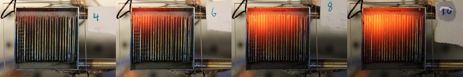
Propane Flowrates from 4-10 Liters per Minute
Current Status
Check out the current state of this project at Mesodyne.com!