Hydrogen Engine
Background
In collaboration with the US Navy, the MIT Lincoln Laboratory has been researching reacting pelletized aluminum fuel with water as an alternative power source for long duration underwater missions. Doping aluminum with gallium allows it to corrode in water without producing a passivating layer. This reaction can be harnessed to produce hydrogen gas at higher energy densities than lithium ion batteries or gasoline can provide. However, this hydrogen gas contains steam and other impurities that make it poorly suited for electric fuel cell use, so we were tasked with exploring internal combustion as a more robust way to convert this hydrogen into electrical power. So
Aluminum + Water
↓
Hydrogen Gas
↓
Engine
↓
Electrical Generator
↓
Onboard Electrical Systems
As other teams were doing extensive work with the aluminium - water reaction, we decided to skip this part of the system and use hydrogen from a tank for our initial system.
Team
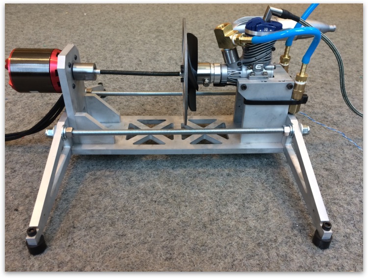
After the initial group selection, my team started exploring the previous research on our project and planning our approach. Our team was made up of four students: Sam took over the engine, Mitch the hardware connections, Dillon the software, and I handled the air and fuel delivery systems. We were given several small two and four stroke engines from the previous semester, along with a 3 phase skateboard motor with braking capabilities that we could use to generate electricity. We shifted responsiblities and assisted each other quite frequently throughout the semester to get this project done.
Air and Fuel Subsystems
We realized very early on that we could harness the wide explosive limits of hydrogen to our advantage. Gasoline only burns when mixed with a fairly precise mixture of air, roughly 4.0 to 75 percent. Outside of this range, an air-fuel mixture will not ignite at all and the engine will completely lose power, so gasoline engines must reduce air and fuel flow simultaneously in order to maintain a flammable mixture and control engine speed. However, hydrogen burns over an incredibly large range of concentrations - 4 percent to 70 percent - so engine speed can be controlled just by controlling the flow of hydrogen. We did some initial engine testing with a flow meter, and then switched to a fuel injector designed for methane to give us a faster response and better engine control.
Code
In order to control this setup, I built an Arduino-based engine control unit. To simplify the software, the speed was controlled by using the inverse of rotational speed, or the time between rotations. As the system is well-damped over most load ranges, simple proportional control worked well for this setup. Using the inverse of speed for the calculations means that the controller is not operating with a linear system, but the simple principle of increasing or decreasing fuel to reach a setpoint still works quite well. Full code is available here.
  // pin numbers:
  const THROTTLEPIN = 7;   // Analog input from potentiometer to control speed.  REQUIRED TO BE AN ANALOG INPUT
  const INJECTORPIN = 12;  // Output to injector circuit.  This goes through a 200 Ω resistor (limits current to 25mA) to a darlington transistor/mosfet base for injection control
  const TIMINGPIN = 2;     // Input from Hall Effect sensor, or equivalently tachometer connection on ignition module. LOOK UP WIRING DIAGRAMS FOR THIS as hall effect sensor pull the sense pin low, but need an external resistor attached to pull it high when not sensing a magnet.
  const LEDPIN = 13;       // Makes the on-board LED turn on whenever the injector does

  // values
  const DT_LOW = 5000;     // Rotation time at full speed, in µs.  = 60,000,000/rpm
  const DT_HIGH = 50000;   // Rotation time at idle, in µs.  = 60,000,000/rpm
  const unsigned long MAXFUEL = 1200;  // microseconds of flow for one cylinder of stochiometric fuel INSERT CALIBRATED VALUE HERE
Fuel Injector Circuit
Our Bosch fuel injector is designed for a peak-and-hold waveform to rapidly open the solenoid then use a lower power to hold it open. We could not find any compact drivers for this, so I made one myself. After doing some research on driver chips and circuit layout, I realized I could achieve the same output as a switched driver with fewer parts that I had on hand if I was willing to burn some extra power with a large resistor (R1).
The capacitor charges while the injector is off, and then provides a 48 volt peak that is regulated to a steady level by R1 for the hold portion of the waveform. Note the Zener diode D1 to prevent voltage spikes that could destroy our MOSFET or other circuit components when the drive signal is turned off.
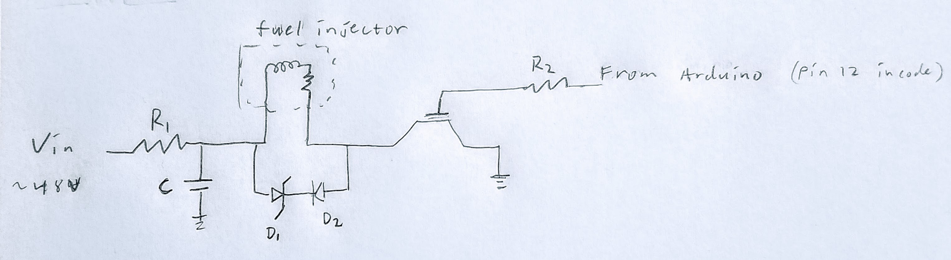
Circuit Diagram
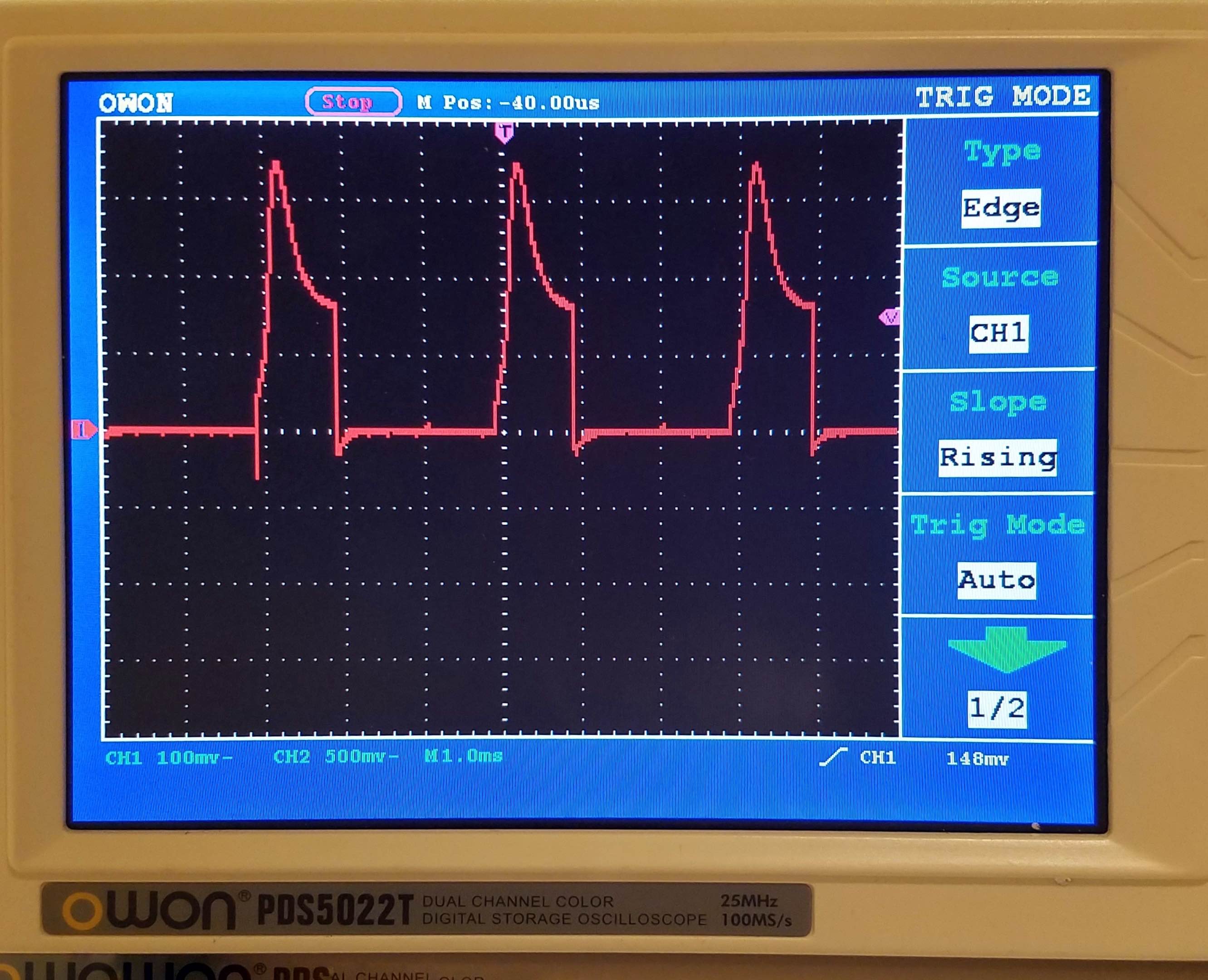
Resultant waveform with three peaks. ECU output at 20,000 rpm and low engine load
Challenges
Like the team before us, we faced some significant challenges. We had numerous driveshaft failures, fuel system failures (due to a sticky solenoid), code failures that would stall our engine or make it run away, and even logistics issues when the lab ran out of hydrogen.
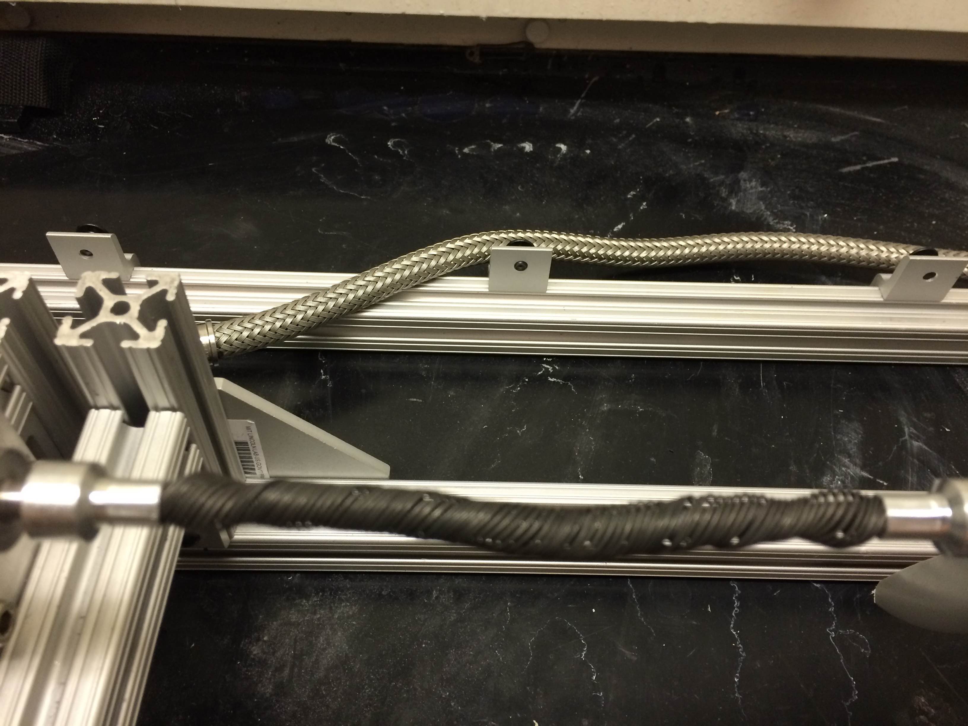
Damaged driveshaft (black) after our engine backfired
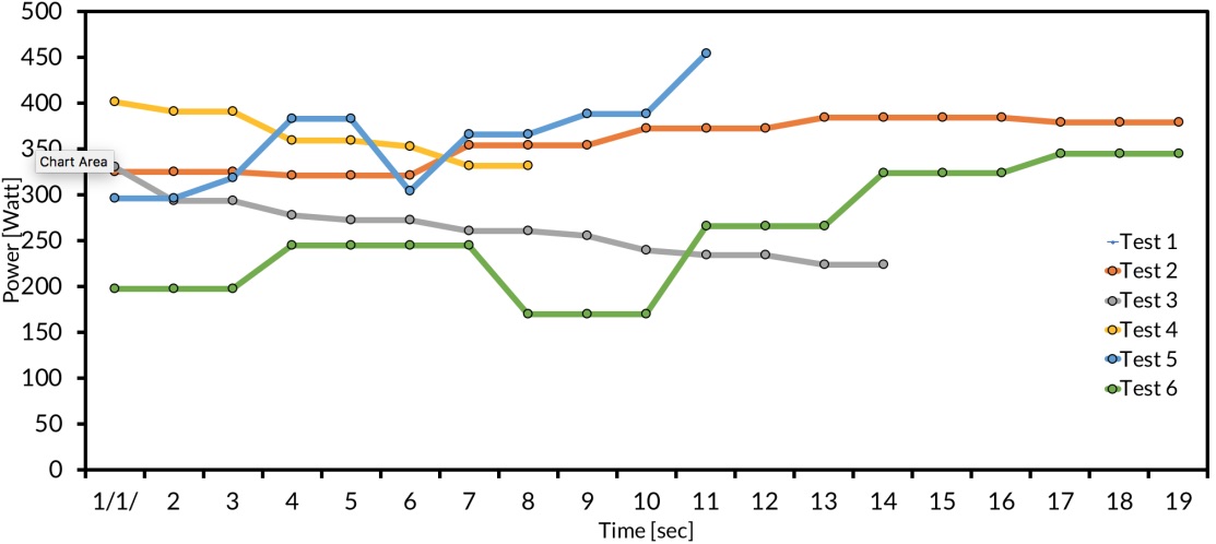
Final Results
We were aiming for a power output of 1 kW, but our power ended up peaking at 35% of full fuel flow, and 35% of expected power output with a thermal efficiency of around 15%. We strongly suspected the low power output was due to poor air-fuel mixing, and both the power and efficiency should increase if this is resolved. However, by the end of this project, we had started from nearly the ground up and built our own engine control unit, control algorithms, frame, safety systems, and hardware connections and we successfully generated electricity from hydrogen.